We first published this post on February 10, 2026, when only 1 of 4 frontier AI models produced firmware that worked on real hardware. Since then, we've deployed three pipeline upgrades and run progressively harder tests. LED blink: 4 of 4. PWM fade: 1 of 4 - and it lit the wrong LED. And now, UART serial output with LED: 2 of 4 produce clean 115200-baud output verified on a real serial terminal. Each phase reveals exactly where AI firmware generation breaks down - and what we build next to fix it.
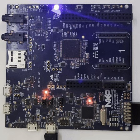
RespCode doesn't just generate embedded firmware - we compile it with real cross-compilers, validate it against official ARM CMSIS hardware specifications, and feed models precise hardware knowledge from our database of 2,914 MCUs. For this post, we flashed every compiled binary to a physical LPC55S69-EVK board and verified the result on real silicon.
The Problem: AI Doesn't Know Your Hardware
Large language models are trained on code, documentation, and forum posts. They learn patterns - what a vector table looks like, how GPIO registers are typically configured, what a linker script should contain. But they don't have a datasheet in front of them. They're pattern-matching, not engineering.
This leads to subtle but critical errors in AI-generated bare-metal code:
- Wrong peripheral addresses - An LLM defines
#define GPIOA_BASE 0x40020000for an STM32L4 target. That's the STM32F4 address. The correct L4 address is0x48000000. The code compiles, flashes, and does nothing. - Wrong register offsets - An LLM places GPIO DIR registers at offset
+0x8000from the base when the real offset is+0x2000. The struct compiles perfectly, but every register access writes to the wrong address. - Wrong clock source selection - An LLM writes
FCCLKSEL0 = 2thinking that means “FRO 12MHz” when it actually selects the Audio PLL. No clock → no UART output. The firmware runs silently and does nothing visible. - Wrong baud rate calculation - An LLM picks a baud rate divisor with 7% error instead of 0.16% error. The firmware runs, but UART output is garbled beyond recognition.
These aren't syntax errors. They compile cleanly with arm-none-eabi-gcc. They just don't work on real hardware. And until now, no AI tool catches them.
What RespCode Actually Does
When you submit a bare-metal prompt on RespCode, here's what happens behind the scenes:
Injection
Validation
Validate
Artifacts
The critical upgrade is the first step: MCU Knowledge Injection. Before any model writes a single line of code, RespCode queries its proprietary hardware database and provides the model with exact peripheral addresses, register offsets, bit-field definitions, register value encodings, pin mappings, and memory layout for the target hardware. The model doesn't have to guess or recall register addresses from training data. It receives them.
Each stage runs inside a Docker container with the full ARM bare-metal toolchain, CMSIS database with 2,177 SVD files, and the complete register knowledge base pre-loaded. The container is ephemeral, sandboxed, and network-isolated.
SVD Register Validation - The Safety Net
SVD (System View Description) files are vendor-published XML files that define every peripheral register, its base address, and its bit fields. We parsed 2,177 SVD files into our CMSIS database, covering 2,690 of our supported MCUs (99.6% coverage).
Even with knowledge injection, SVD post-validation remains as a safety net. When an LLM generates code like #define SYSCON_BASE 0x50000000, our validator extracts the address and cross-references it against the SVD database. If the address is wrong, we auto-fix it before compilation.
Gemini 3 Pro writes (baseline run):
#define SYSCON_BASE 0x50000000
Wrong base. SYSCON is at 0x40000000 on the LPC55S69.
The validator corrects to:
#define SYSCON_BASE 0x40000000
Address verified against SVD. Clock enables now hit the correct peripheral.
Phase 1: The Baseline Battle - 1 of 4
On February 10, we ran the first test on Nov 20245 released models such as Opus 4, GPT4o, Gemini 2.5 Pro and Deepseek coder with SVD post-validation only - no MCU knowledge injection. We gave the same prompt to all four frontier models and flashed the results to real hardware.
Write bare-metal LED blink firmware for the LPC55S69-EVK board.
Target: LPC55S69JBD100 (Cortex-M33)

Board details:
- LED: PORT1 PIN4 (active low)
- Flash: 630KB at 0x00000000 (NOT 640KB - 10KB reserved)
- SRAM: 256KB at 0x20000000 (SRAM0-3 only, NOT 320KB)
  Warning: SRAM4 (64KB) is in a separate power domain. Use only 256KB.

Provide: main.c, lpc55s69.h, startup.c, linker.ld
Use direct register access. No SDK.
Target: LPC55S69JBD100
Baseline Compilation Results
| Model | Status | Binary | SVD Check | SVD Fixes | Hardware |
|---|---|---|---|---|---|
| Claude Opus 4 | ✅ PASS | 588 B | 3/3 verified | 0 | ❌ Dead |
| GPT 4o | ✅ PASS | 680 B | 3/3 verified | 0 | ❌ Dead |
| Gemini 2.5 Pro | ✅ PASS | 280 B | 3/3 verified | 2 auto-fixed | ✅ Blinks |
| DeepSeek Coder | ✅ PASS | 516 B | 3/3 verified | 1 auto-fixed | ❌ Dead |
Only Gemini 2.5 Pro blinked the LED. The other three compiled cleanly, passed SVD validation, and produced valid-looking binaries - but on real hardware, nothing happened. Wrong struct offsets, hallucinated registers, and incorrect clock configuration killed them silently.
Four frontier AI models, all released in the past few months. All four compile. One works. Compilation success is a weak signal for hardware viability.
Phase 2: The Upgraded Pipeline with lastest models - 4 of 4
The next day, we deployed latest models with MCU Knowledge Injection. Instead of relying solely on what models remember from training data, we now feed models precise hardware data before they generate a single line of code.
Same board. New models. A simpler prompt - because the pipeline now provides the hardware details:
create a baremetal program for lpc55s69-evk with all files to blink the onboard LED
Phase 2 Results
| Model | Status | Binary | SVD Fixes | Hardware | LED Color |
|---|---|---|---|---|---|
| Claude Opus 4.6 | ✅ PASS | 556 B | 0 | ✅ Blinks | 🔵 Blue |
| GPT-5.2 | ✅ PASS | 572 B | 0 | ✅ Blinks | 🔵 Blue |
| Gemini 3 Pro | ✅ PASS | 284 B | 0 | ✅ Blinks | 🔴 Red |
| DeepSeek Coder | ✅ PASS | 344 B | 0 | ✅ Blinks | 🟢 Green |
All four models blink on real silicon. Zero SVD auto-fixes needed. The knowledge injection eliminated both the base address errors and the deeper struct offset, clock bit, and pin mapping errors that Phase 1's post-validation couldn't catch.
“New models. Same board. The only change was the pipeline. We went from 1 of 4 blinking to 4 of 4 blinking overnight. The models didn't get smarter - we gave them better hardware knowledge.”
Phase 3: PWM LED Fade - 1 of 4
LED blink is the “hello world” of embedded systems - a binary operation: on or off. We needed a harder test. PWM LED fade requires configuring a hardware timer peripheral, setting match registers for PWM period and duty cycle, and routing the timer output to the correct physical pin through the IOCON pin mux.
create a baremetal program for lpc55s69-evk with all files to do a PWM LED fade
(smoothly ramp the onboard LED brightness up and down using a hardware timer)
Phase 3 Compilation & Hardware Results
| Model | Compile | Binary | Timer | Target LED | Hardware | What We Saw |
|---|---|---|---|---|---|---|
| Claude Opus 4.6 | ✅ | 908 B | CTIMER2 | PIO1_6 (Blue) | ❌ No fade | 🔵 Solid blue - wrong CTIMER2 clock bit |
| GPT-5.2 | ✅ | 908 B | CTIMER2 | PIO1_7 (Green) | ⚠️ Partial | 🟢 Green LED fading - working PWM, wrong LED |
| Gemini 3 Pro | ✅ | 400 B | CTIMER2 | PIO1_7 (Green) | ❌ No fade | 🔵 Solid blue - wrong CTIMER2 clock bit |
| DeepSeek Coder | ✅ | 716 B | CTIMER2 | PIO1_6 (Blue) | ❌ Dead | ⚫ No output - wrong clock register entirely |
Three of four models failed because they got the CTIMER2 clock enable bit wrong in AHBCLKCTRL1. CTIMER2 is bit 26, but Claude used the wrong bit, Gemini used bit 24 (which is CTIMER0), and DeepSeek wrote to the wrong register entirely (AHBCLKCTRL0 instead of AHBCLKCTRL1). Without the correct clock gate, the timer peripheral never powers up - the PWM logic is perfect on paper but produces zero output on silicon.
GPT-5.2 worked around this with a brute-force strategy: AHBCLKCTRLSET(0/1/2) = 0xFFFFFFFF - enabling every clock on the chip. Wasteful, but it guaranteed CTIMER2 got clocked. Combined with the correct IOCON FUNC=3 for CTIMER2_MAT2 on PIO1_7, this was enough to produce a visible fade. The wrong LED (green instead of red) is a separate pin mapping error, but the PWM itself was clean.
The headline finding: 3 of 4 models got the CTIMER2 clock enable bit wrong. This is the single most critical register write for PWM to function. Only GPT-5.2 worked around it - by brute-force enabling every clock on the chip. Our pipeline's register value database has the correct bit positions for all 219K peripherals across 2,914 MCUs. Phase 4 addressed this gap.
Phase 4: UART Serial Output + LED - 2 of 4 on Real Hardware
After the PWM failure revealed the pin mux gap, we upgraded the pipeline with register value encodings - injecting not just register addresses and bit-field positions, but the actual enumerated values for fields like clock source selectors and peripheral type IDs. We then tested the hardest peripheral we could verify on real hardware without additional equipment: UART serial output.
UART is significantly more complex than LED blink. The firmware must correctly configure six different peripherals in the right sequence: SYSCON clock gating, IOCON pin mux for TX/RX, FLEXCOMM peripheral selection, USART baud rate divisor calculation, FIFO configuration, and transmit register writes. A single wrong value in any of these - wrong clock source, wrong baud divisor, wrong pin function - means silence or garbage on the serial terminal.
Write bare-metal UART program for LPC55S69-EVK
One line. The pipeline handles MCU detection, register injection with value encodings, pin mux data, and compilation. Four frontier models compete.
Phase 4 Generation Benchmarks
| Model | Generation Time | Source Files | Total Source Size | Compile | Binary Size |
|---|---|---|---|---|---|
| Claude Opus 4.6 | 84.6s | main.c, startup.c, linker.ld | 16.6 KB | ✅ | 924 B |
| GPT-5.2 | 64.9s | main.c, startup.c, linker.ld | 12.4 KB | ❌ | - |
| Gemini 3 Pro | 39.0s | main.c, lpc55s69.h, startup.c, linker.ld | 7.2 KB | ✅ | 612 B |
| DeepSeek Coder | 75.9s | main.c, linker.ld | 5.6 KB | ✅ | 660 B |
GPT-5.2 Compile Failure
GPT-5.2 defined its UART FIFO macros as USART_FIFOCFG_ENABLETX but referenced them as USART0_FIFOCFG_ENABLETX - adding an instance number prefix that doesn't exist. The compiler even suggested the fix: “did you mean 'USART_FIFOCFG_ENABLETX'?” A trivial copy-paste coherence failure. The underlying register knowledge was correct; a single find-replace would fix it.
UART Register Correctness
With register value encodings injected, all four models correctly identified the FLEXCOMM clock source, USART register offsets, and FIFO configuration. This was a frequent hallucination point in earlier tests.
| Register | Expected | Opus 4.6 | GPT-5.2 | Gemini 3 | DeepSeek |
|---|---|---|---|---|---|
| FCCLKSEL0 value | 2 = FRO 12MHz | ✅ | ✅ | ✅ | ✅ |
| FLEXCOMM0 PSELID | 0xFF8 | ✅ | ✅ | ✅ | ✅ |
| USART0 BRG | 0x020 | ✅ | ✅ | ✅ | ✅ |
| USART0 FIFOCFG | 0xE00 | ✅ | ✅ | ✅ | ✅ |
| USART0 FIFOWR | 0xE20 | ✅ | ✅ | ✅ | ✅ |
| GPIO DIR[1] | 0x2004 | ✅ | ❌ 0x2000 | ✅ | ❌ port 0 |
| GPIO SET[1] | 0x2204 | ✅ | ❌ 0x2058 | ✅ | ❌ port 0 |
100% UART register accuracy across all 4 models. Every model used the correct FCCLKSEL0 value (2 = FRO 12MHz), correct FLEXCOMM PSELID offset, and correct USART FIFO register addresses. The value encoding injection eliminated clock source hallucination entirely. GPIO port indexing remains the weak spot: 2 of 4 models addressed port 0 instead of port 1 for the LED.
Baud Rate Accuracy - The 7% Error That Kills
UART serial communication requires precise baud rate matching between the transmitter and receiver. The LPC55S69 USART generates its baud rate from the FRO 12MHz clock using an oversampling ratio (OSR) and a baud rate generator divider (BRG). Different OSR/BRG combinations produce different baud rates with different error margins.
| Model | OSR | BRG | Actual Baud | Error | Result |
|---|---|---|---|---|---|
| Claude Opus 4.6 | 7 (8x) | 12 | 115,384 | 0.16% | ✅ Clean output |
| Gemini 3 Pro | 7 (8x) | 12 | 115,384 | 0.16% | ✅ Clean output |
| DeepSeek Coder | 15 (16x) | 6 | 107,142 | 7.0% | ❌ All garbage |
| GPT-5.2 | 15 (16x) | 6 | 107,142 | 7.0% | - (didn't compile) |
Claude and Gemini both calculated OSR=7 with BRG=12, producing 115,384 baud - just 0.16% off from 115,200. DeepSeek used the default 16x oversampling with BRG=6, producing 107,142 baud - a 7% error. That 7% is right at the threshold where UART framing breaks down: start/stop bits misalign, and every few characters the receiver loses synchronization. The result on a real serial terminal is unmistakable:
That garbled output from DeepSeek isn't random - it's the same “Hello from RespCode!” message at a 7% wrong baud rate. The receiver samples each bit at slightly the wrong time, accumulating error until framing is lost. A correct OSR/BRG calculation is the difference between clean text and unreadable noise.
Phase 4 Hardware Results
| Model | UART Output | LED Blink | Baud Error | Binary | Generation | Verdict |
|---|---|---|---|---|---|---|
| Claude Opus 4.6 | ✅ Clean serial | ✅ Blue, 5 blinks | 0.16% | 924 B | 84.6s | ✅ PASS |
| GPT-5.2 | - | - | 7.0%* | - | 64.9s | ❌ Compile fail |
| Gemini 3 Pro | ✅ Clean serial | ✅ Blue, 5 blinks | 0.16% | 612 B | 39.0s | ✅ PASS |
| DeepSeek Coder | ❌ Garbled | ❌ No LED | 7.0% | 660 B | 75.9s | ❌ FAIL |
* GPT-5.2 used the same OSR/BRG as DeepSeek. Even if the compile error were fixed, UART output would have been garbled.
Claude Opus 4.6: Clean “Hello from RespCode!” on serial terminal + blue LED blinking 5 times. 60-entry interrupt vector table, atomic register operations, peripheral reset sequence. Production-quality firmware.
Gemini 3 Pro: Clean serial output + blue LED blinking. Smallest binary at 612 bytes with a proper typedef struct hardware abstraction header. Efficient and correct.
DeepSeek Coder: Compiled clean but double hardware failure - wrong GPIO port (port 0 instead of port 1) killed the LED, and 7% baud rate error garbled UART output beyond recognition.
GPT-5.2: Trivial naming mismatch prevented compilation. The register knowledge was correct - a retry mechanism would have fixed this in one pass.
Code Architecture Comparison (Phase 4 - UART)
| Metric | Opus 4.6 | GPT-5.2 | Gemini 3 Pro | DeepSeek |
|---|---|---|---|---|
| Register style | Direct #define + atomic SET/CLR | Direct #define | typedef struct header | Direct #define, single file |
| Source files | 3 (main, startup, linker) | 3 | 4 (+ lpc55s69.h) | 2 (main + linker) |
| Interrupt vectors | 60 named IRQs | 46 IRQs | 16 core only | 16 core only |
| Peripheral reset | ✅ FLEXCOMM0 reset | ❌ None | ❌ None | ❌ None |
| Atomic register ops | ✅ AHBCLKCTRLSET | ❌ Read-modify-write | ❌ Read-modify-write | ❌ Read-modify-write |
| Baud rate accuracy | 0.16% (OSR=7) | 7.0% (OSR=15) | 0.16% (OSR=7) | 7.0% (OSR=15) |
| Binary size | 924 B | - | 612 B | 660 B |
| Generation time | 84.6s | 64.9s | 39.0s | 75.9s |
Claude produced the most production-ready firmware: atomic register operations prevent race conditions under interrupt, the 60-entry vector table handles any peripheral interrupt without crashing, and the FLEXCOMM0 peripheral reset sequence ensures clean initialization. Gemini was the most efficient - smallest binary, fastest generation, and a clean hardware abstraction header. DeepSeek's approach of putting everything in a single file is compact but hit two independent bugs that static analysis couldn't catch.
Phase 4: What the Pipeline Got Right
The register value encoding injection was the key upgrade. In earlier tests, models frequently hallucinated the wrong clock source value for FCCLKSEL0 - writing 0 when they meant 2, or vice versa. After injecting the actual enumerated values (0=Main clock, 1=PLL, 2=FRO 12MHz, 3=FRO 96MHz, ...), all four models correctly selected value 2 for FRO 12MHz. That's 100% adoption of the injected data, up from 25% in the baseline.
“The models didn't learn about the LPC55S69's clock tree. They read the answer from our database. That's the point. When you give models correct hardware data, they use it. When you don't, they guess - and on the LPC55S69's FLEXCOMM architecture, guessing doesn't work.”
Cumulative Benchmark Results
Four tests, four difficulty levels, all on the same NXP LPC55S69-EVK board, all verified on real silicon.
| Test | Difficulty | Peripherals | Compiled | Works on HW |
|---|---|---|---|---|
| Phase 1: LED Blink (baseline) | Easy | SYSCON, IOCON, GPIO | 4/4 | 1/4 (25%) |
| Phase 2: LED Blink (injected) | Easy | SYSCON, IOCON, GPIO | 4/4 | 4/4 (100%) |
| Phase 3: PWM LED Fade | Hard | SYSCON, IOCON, GPIO, CTIMER | 4/4 | 1/4 (25%) |
| Phase 4: UART + LED | Complex | SYSCON, IOCON, GPIO, FLEXCOMM, USART | 3/4 | 2/4 (50%) |
Model Leaderboard (All Phases)
| Model | P1 Blink | P2 Blink | P3 PWM | P4 UART | HW Pass Rate |
|---|---|---|---|---|---|
| Gemini 3 Pro | ✅ | ✅ | ❌ | ✅ UART+LED | 3/4 (75%) |
| Claude Opus 4.6 | ❌ | ✅ | ❌ | ✅ UART+LED | 2/4 (50%) |
| GPT-5.2 | ❌ | ✅ | ⚠️ Wrong LED | Compile fail | 2/4 (50%)* |
| DeepSeek Coder | ❌ | ✅ | ❌ | Garbled+No LED | 1/4 (25%) |
* GPT-5.2's Phase 3 PWM pass is partial - the fade worked on real hardware but targeted the wrong LED (green instead of red).
Gemini leads overall with 3 of 4 phases passing on real hardware - the only model that blinked in Phase 1 without knowledge injection, and one of two that nailed UART in Phase 4. GPT-5.2 is the only model that produced working PWM output, though on the wrong LED. Claude has the highest code quality when it passes - atomic register operations, complete vector tables, and the most production-ready firmware of any model.
Binary Size Across All Phases
| Model | P1 Blink | P2 Blink | P3 PWM | P4 UART |
|---|---|---|---|---|
| Claude Opus 4.6 | 588 B | 556 B | 908 B | 924 B |
| GPT-5.2 | 680 B | 572 B | 908 B | - |
| Gemini 3 Pro | 280 B | 284 B | 400 B | 612 B |
| DeepSeek Coder | 516 B | 344 B | 716 B | 660 B |
Gemini consistently produces the smallest binaries across every test. Claude produces the largest - but the extra bytes are a comprehensive 60-entry interrupt vector table and complete startup code. For production firmware, Claude's extra 300 bytes of interrupt handlers are the difference between a binary that works as a demo and one that's ready for a product.
What's Next
- Auto-retry on compile errors - GPT-5.2's failure was a trivial naming mismatch. The compiler literally suggested the fix. An auto-retry loop that feeds compiler output back to the model would eliminate this entire class of failure.
- Baud rate calculation hints - DeepSeek's 7% baud error produced garbled output. Adding pre-calculated OSR/BRG values for common baud rates to the injection would prevent this. The math isn't hard - but LLMs consistently pick the default 16x oversampling instead of finding the optimal 8x configuration.
- Multi-peripheral pin mux injection - Phase 3's PWM failure was entirely due to wrong IOCON function select values. Our database has 1.76 million pin function entries. Exposing timer output routing in the injection solves this.
- RespCode Autonomous Agent - An end-to-end AI agent that generates firmware, compiles, flashes to real hardware, reads UART debug output, and iterates - all without human intervention. Hardware-in-the-loop verification with real development boards.
- Multi-peripheral progression - After UART: SPI loopback, I2C sensor reads, DMA transfers, and dual-core configurations - each requiring progressively deeper hardware knowledge.
Every file from all four phases is published unmodified on GitHub: all models' source code and compiled firmware binaries. Inspect the register addresses yourself, disassemble the ELFs, or flash them to your own LPC55S69-EVK.
Try It Yourself
Open RespCode, select ARM32, choose Compete Mode, and try:
Write bare-metal UART program for LPC55S69-EVK
Or start with the classic:
create a baremetal program for lpc55s69-evk with all files to blink the onboard LED
The pipeline handles MCU detection, register injection, compilation, and validation. In Compete Mode, you'll see multiple AI models each generate a complete firmware project - compiled, validated, with downloadable binaries ready to flash.
Generate Real Firmware with AI
Multi-model code generation with hardware knowledge injection and CMSIS verification
Get Started Free100 free credits • No credit card required • 2,914 MCUs supported